Posts Tagged SketchUp
Getting A Little Wired
Posted by Adam A. Ries in DIY, Home Improvement, Interior Design on June 25, 2014
Although I do admit to keeping cold beer in the fridge, no, this post is not about my social drinking habits. I’m referring to the work at the house over the last few weeks. It started like this:
I have 2 great friends who had previously committed to helping with any renovation-related tasks; “just ask,” they kept saying. Up until this point, I mostly knew what I was doing or was able to watch instructional videos through YouTube or This Old House to learn what I needed. But it was getting time to wire up new light fixtures and outlets in the bathroom. So I called in the big guns, aka Paul and Dennis. Paul is a former trade electrician, and now part of the maintenance department at a local manufacturing company. Dennis has every construction tool known in the industry, along with knowing all there is to know about construction and especially electricity; he now owns a printer supply store here in town. They both showed up the Saturday before last, toolboxes in hand, and scratched their heads simultaneously at the sight of the existing electrical panel.
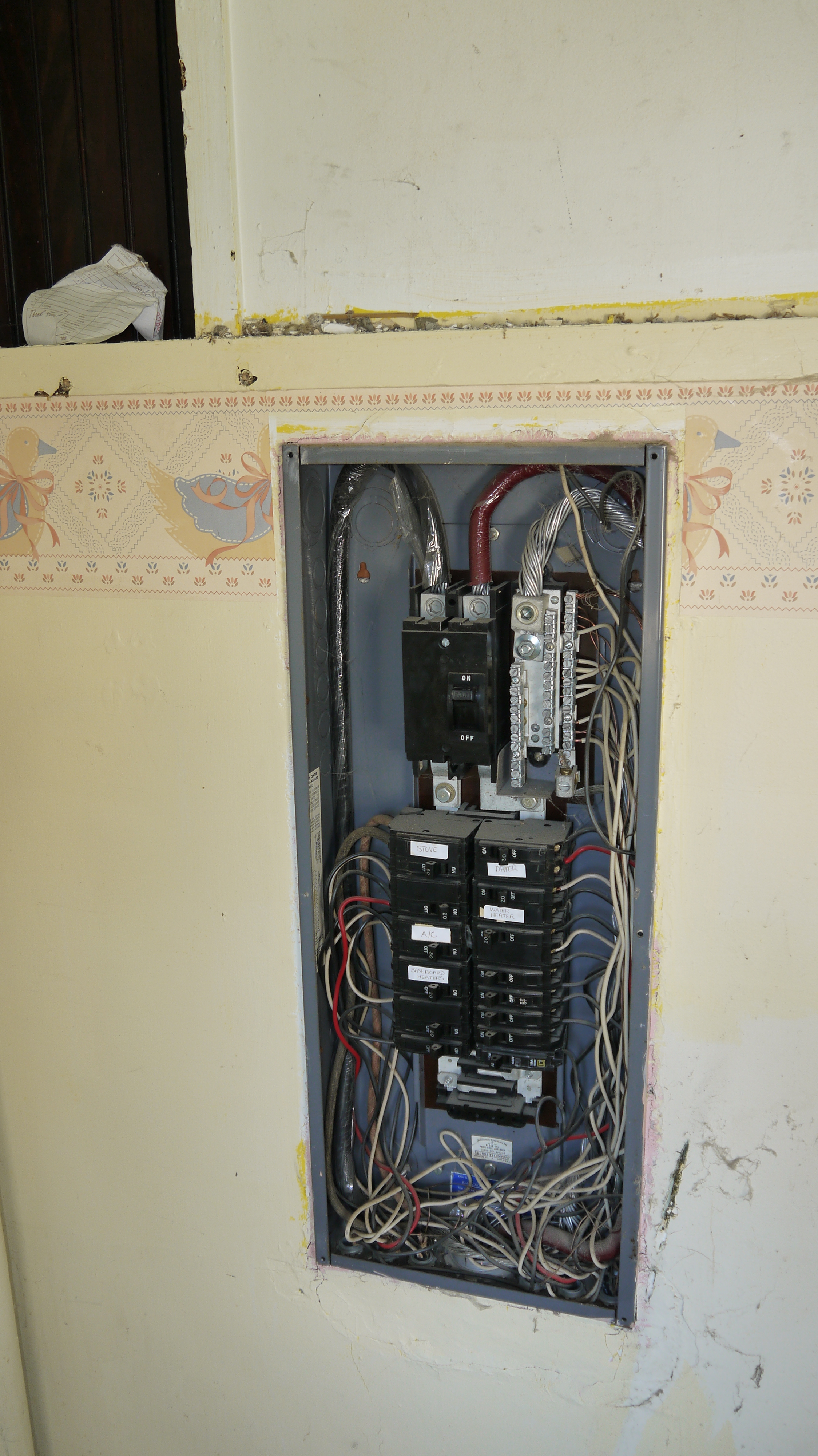
The rats nest of wires was enough to make me dizzy, and they felt the same. Now here’s the interesting part: only 1 breaker in this entire panel is in the “on” position, yet throughout the entire house every outlet and light fixture is working – including the garage and outbuilding. Other than the range, dryer, and heaters, I have no idea where or what the remaining 7 breakers must serve.
So while Paul taught me how to install outlet boxes and the tricks of the trade for running Romex wire, Dennis went to town stripping out the panel box. They both agreed the 200 amp service box is in good shape and enough space to serve the house, they wanted to organize the wire maze and distribute power in the house onto multiple breakers, the way a new house would be wired.
In the bathroom, I thought I had a reasonable electrical layout planned (2 outlets near the light switch), but both of Dennis & Paul’s wives and another female friend agreed that I should plan on additional outlets for all of the crazy hair and beauty products women use everyday and apparently need a half-dozen outlets to power. I settled on a double outlet box on either side of the vanity mirror, a straight line down from where I had already planned for light sconces flanking the mirror.
This quick 3D model was made in SketchUp, a great tool for quick rendering to plan out a space or construction detail.

This photo shows the double sets of outlets, with the light fixture boxes above each one, and the light switches on the wall to the right. One switch will control the light sconces beside the mirror, the other is 2 small switches so I can independently turn on and off the ceiling exhaust fan & light. The bathroom did not previously have an exhaust fan. Putting one in was just a matter of finding the center of the room and then finding the nearest ceiling joist. I drilled a hole from up above so I knew where the edge of the joist was, then used that as my starting point for drawing a square on the ceiling the size of the fan housing box. A jigsaw cut the plaster and lathe, and the box dropped right into place from above the ceiling. Paul held the box flush with the plaster ceiling down below while I used drywall screws up above to secure it to the ceiling joist. Once it was wired, I left it go until just yesterday when I finally drilled a 4″ hole in the gable end of the house and vented the fan outside using a dryer vent cover and 4″ flexible dryer hose.
Opposite of the bathroom in the laundry/utility room, we wired a GFCI outlet for the washing machine, a 220 volt dryer outlet, and rewired the laundry room ceiling light using 3-way light switches. I can turn the light on from the kitchen doorway like before, but now I can also turn on the light as soon as I come into the house from the back door. In the same bay at the back door, we left space for additional switches for a new back porch light, outdoor light, and outlet for the utility room. Having all the switches in one box will look so much more organized than 1 beside the door and 2 others on the adjacent wall, all at different heights currently.

In the process, Dennis made sure everything was split onto appropriate amount of breakers in the electrical panel, and even labeled each breaker space! And did I mention that we are using outlet boxes? As in, every outlet or switch is housed correctly in a box. Why do I emphasize that? Of the entire house, we have only found 3 or less receptacles boxes. All the other switches or outlets are simply a hole cut in the wall, bare wires touches plaster, lath, wood paneling, baseboard, etc. That’s perfectly safe, right? NO! Even our local Fire Chief remarked that he isn’t sure how the place didn’t catch fire at some point. I know why: because this house was waiting on me.

And here is how the breaker panel looks now – complete with hand-drawn breaker diagram on the plaster wall to the right. Each wire has a purpose and a home. Don’t ask me where those additional wires at the bottom must lead, because the whole house still has power even though those have been pulled out of the box. They are probably individual baseboard heaters, but I still need to trace each one. Eventually, Paul and Dennis assure me they are going to help me get the entire house re-wired. From what they’ve taught me so far, it shouldn’t be too bad; the majority of it seems finished with the bathroom and laundry out of the way. The rest of the rooms will just have regular outlets, light switches, and ceiling lights – replacing what’s already there – and adding all necessary receptacle boxes!
Not yet floored
Posted by Adam A. Ries in DIY, Home Improvement, Interior Design on May 10, 2014
Finished the last of the plumbing supply lines today, but no, the bathroom still does not have a floor. Because I spent all morning loading and hauling 2 truck loads full of scrap metal and old pipes to the local metals recycling center. The new company that opened a few years ago is much more competitive on price than another local company, and they have much better customer service when I called to get metal prices over the phone. That better customer service was experienced in person, too.
All together there was galvanized steel duct, cast iron pipes, steel pipes, copper pipes, brass fittings, aluminum cans, steel cans, buckets of scrap metal (pulled nails, screws, other small parts & pieces), sheet aluminum, the old steel furnace housing, and the cast iron furnace heater.
Two trips and one small cut on the forearm later, I walked out with cash in hand. Not to shabby, considering half of what I scrapped in was just laying under the house. FREE. All I had to do was carry it out and load it onto a truck. In total, the cash I got was close to half of the amount I’ve invested in PEX hoses & fittings for the new supply lines. Nothing like tearing out old plumbing to pay for the new! (Whoa: imagine if every DIY project was like that… what you tore out would pay for half of the new project?)
Now it’s onto choosing and installing a water heater, but also installing the drain lines. The only portion that concerns me is the home’s original cast iron sewer drain. I’m not sure how to connect the new PVC drains into that, to end up with a leak-free drain that will last. So I need to make friends with a plumber and ask for help.
So now for a peak at the new bathroom layout!
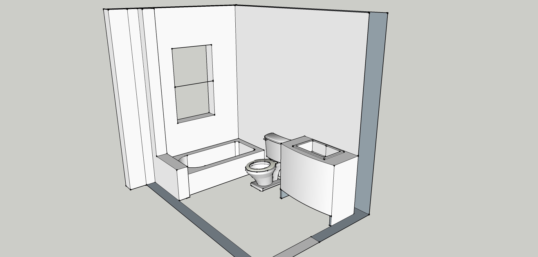
Below is the original layout, with the tub and toilet so close together, sitting on the stool meant soaking your feet for a bath.

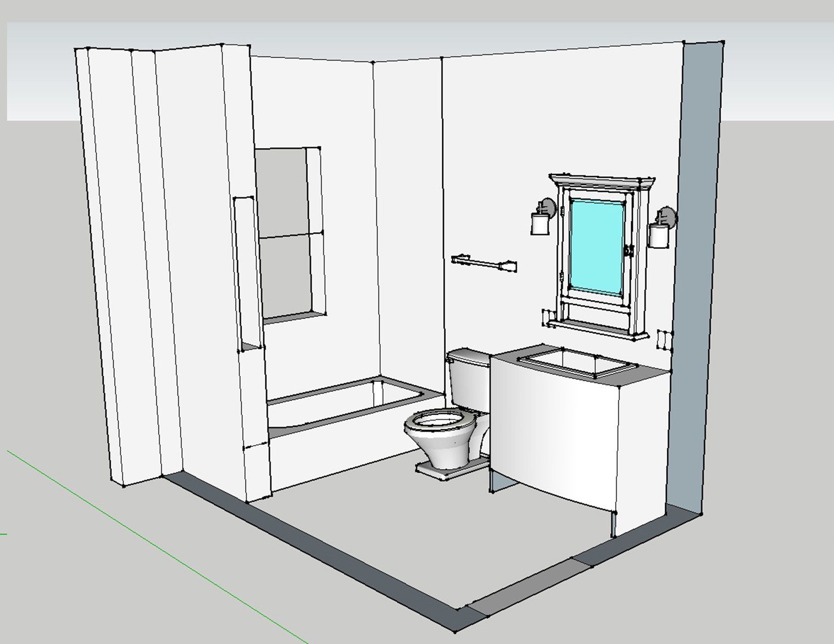
Here is how I am planning the new bathroom. I love Google SketchUp for quick floor-planning and 3-D modeling. Its quick to learn, but if you want to spend more time you can actually create a very detailed 3-D rendered model of a space or object. I literally drew out 12 different plans of how to move the 3 bath fixtures around in this space, and this naturally came out as the best solution.

You can see the door through the wall at the right, and the window above the tub on the left. Overall, I think this floor-plan of the bath feels so much more open. All the bathroom drains will be along one wall, which I hope will be easy to connect.
The bathroom is 68″ wide, and the tub is only 60″ long. This leaves a 8″ space between the tub and the finished wall. I tried several different versions of shelves, skinny cabinets, or other storage in this narrow nook, but decided on a knee wall to act as a ledge for bath bottles and such. The ledge doesn’t go directly to the window wall. Instead, there is a small chase to run the drain vent up though the ceiling and out the roof.
There will still be room on the wall opposite the toilet for a narrow storage cabinet if I need one. And although I didn’t show all the detail here, I am planning on a built-in mirrored medicine cabinet above the vanity, and another shallow in the wall to the right of the sink.
While drawing out this plan, I took some criticism for the idea of keeping the window. In this layout, the window will be in the shower area. I found several answers online on how to install a water-tight shower window, and they were all nearly the same. This instructional page & photo is what I will be following.
I just think natural daylight and ventilation is too important to close-in the window, no matter the room. Secondly, the window opens to the backyard, more than 50 feet from an alley, and another 50 feet to a neighboring house. If I really feel concerned about privacy, I can order the new window with opaque glass.
If you’re gonna do it,
Posted by Adam A. Ries in DIY, Furniture on November 3, 2010
DO IT RIGHT!
That is my mantra. I like to see the end results just as much as anyone else, but a hurried project will look hurried. That being said, this is Post 2.5 of a 3 post series of the Roadside Redo cabinet project Click here to read Part 1 in this series, or here to read Part 2.
When this cabinet was originally built, the top wide drawer was made to slide on wooden rails inside the cabinet walls. This is a very simple solution for a drawer slide but by far not the best solution for such a wide, heavy drawer such as this cabinet features. On its original slides the drawer would not have extended from the cabinet very easily; it would have torqued from one side to the other when pulled out or pushed in. Also, once extended more than halfway, the drawer would have begun to fall out of its opening, potentially falling onto the floor (or someones feet) if pulled out all the way. Below is a SketchUp model of what the left cabinet slide looked like originally, highlighted in red.

With all the time I have invested in refinishing this cabinet I wanted a smooth sliding drawer that would operate easily even when weighted down by objects stored inside. For this purpose I purchased drawer slides from my local hardware store. Simple drawer slides come in various lengths; my local hardware store had them in even numbered lengths from 14″ to 24″. My cabinet is just over 17″ deep, so I chose a set of 16″ drawer slides. They came with 2 drawer rails, 2 cabinet rails, all required screws, and detailed instructions (in multiple languages).

Because I had already assembled the cabinet face frame, I would have to make a slight adjustment for the new drawer slides. The instructions call for the drawer opening to be between 1″ and 1 + 1/16″ wider than the drawer width. The width of my drawer was already 38 + 3/4″, and making it narrower would be far too much work. Instead I chose to make notches out of the face frame to allow for the metal drawer slides to operate.
The opening in the cabinet face for the drawer was 39 + 1/16″, and I needed to make it 39 + 3/4″. This meant cutting a 3/8″ notch out of each side of the face frame. Once the drawer is in place, these notches would be practically unnoticeable as they would be hidden by the perimeter of the drawer face. Below is the left of the cabinet opening showing in red where I needed to cut out the notch.

I cut these notches very carefully with a handheld jigsaw, trying to keep them as square as possible; the notches will be noticeable when the drawer is opened and I want them to look very clean. I made the notches just taller than the height of the metal slides. You can see how these notches allow for the metal slides in the photo below.

And in the next photo, the drawer is in! It slides quite well, but is a bit difficult to lift in and out; I don’t plan on removing the drawer very often so it will work fine for me.

Ignore how bright the wood looks in these photos, I was working in a poorly lit garage and the flash seems to think the wood is much lighter and uglier in color than it really is. But you will see that in the Final Reveal in the last post of this series, where I will explain what finish I chose and how to apply it, secure the glass in the doors, and put on all the hardware.
